Introduction
The USB Cable Tester is a diagnostic tool designed to verify internal wiring of various USB cables with minimum length of 12 inches or 30 centimeters. This manual provides instructions for use of the tester.
Overview
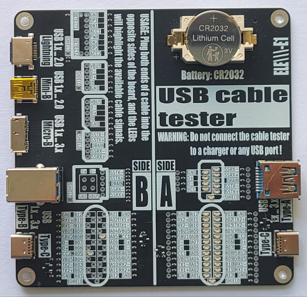
Power Source: CR2032 Lithium Cell (3V).
Purpose: Test pin continuity and identify passive USB cables.
Connector combinations supported:
A-side:
- Type-C
- Type-A / Type-A Super Speed
B-Side:
- Type-C
- Type-B / Type-B Super Speed
- Micro-B / Micro-B Super Speed
- Mini-B
- Lightning
It passively illuminates LEDs showing which signals (power, data, configuration, shield) are connected between the cable ends.
Board Layout
– Pin mapping LED matrices
– Label overlays for signal identification
– Test points for a USB cable pin to pin continuity tests
⚠️ WARNING: Before continuity tests with a multimeter the battery (CR2032) must be removed!
Safety Warnings
- Use only with unpowered cables! DO NOT connect this tester to a USB charger, PC, or live USB host. Connecting the tester to a charger or active USB port may damage the device or cause injury.
- Keep out of reach of children. It is not a toy.
- Handle with Care: Avoid short-circuiting pins or exposing the board to moisture.
- The board is not designed to carry power or signals – it’s a passive tester.
How to Use and Interpret Results
- Ensure the tester is powered by the CR2032 battery.
- Testing a Cable:
- Select the appropriate USB ports on the tester matching your cable type (e.g., Type-C to Type-C).
- Connect one end of the cable to a port on Side A.
- Connect the other end to the corresponding port on Side B.
- Interpreting Results:
- Visually inspect the LED indicators. Check for consistent pin connections (e.g., Power: VBUS, GND. Data: D+, D-…).
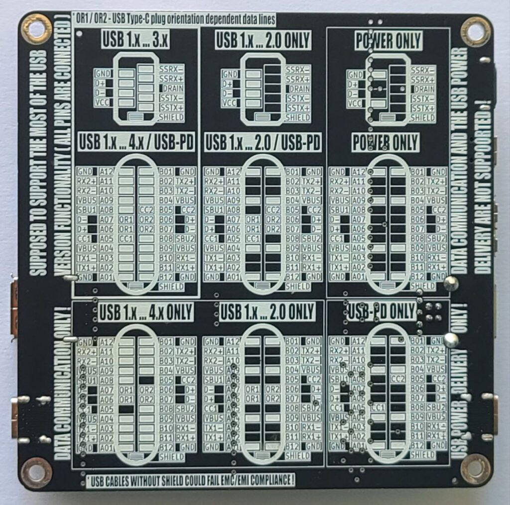
- Use the reference matrix (the tester board bottom side) to identify the cable.
- Once testing is complete, unplug both ends of the USB cable to preserve battery life.
Understanding LED Indicators
- Each LED indicates the presence of a connected signal path through the cable, except for the configuration lines CC1 and CC2.
- LED ON = continuity exists on that line
- LED OFF = no connection on that line
- The CC1 and CC2 LEDs indicate the presence of pull-up resistors (Rp) built into the cable on the Downstream Facing Port (DFP) – typically the host:
- 56 kΩ (USB 2.0: 500mA, USB 3.x: 900mA)
- 22 kΩ (1.5A)
- 10 kΩ (3.0A)
The Rp resistor defines the advertised current to the Upstream Facing Port (UFP) – typically the device – which uses a 5.1 kΩ pull-down resistor (Rd). This combination forms voltage levels of approximately 0.66 V, 1.1 V or 1.7 V from a 5 V DC source.
- CC1 and CC2 connections in the Type-C to Type-C cables, as well as pin to pin shorts are not indicated by LEDs. These can be tested using a multimeter in continuity test mode.
⚠️ Refer to the battery removal warning mentioned above before testing.
Signal Reference Guide
|
Signal |
Description |
| VBUS |
Bus power line |
| GND |
Ground for power return |
| D+, D- |
USB 2.0 data lines (One – unshielded twisted pair) |
| TX1+/-, RX1+/-, TX2+/-, RX2+/- |
USB 3.x SuperSpeed lines (Four – shielded differential pairs) |
| CC1 / CC2 |
Configuration channels (USB-PD) |
| SBU1 / SBU2 |
Sideband use (USB-C) |
| Shield |
Cable external braid |
The USB Type-C connector supports multiple standards, each with distinct signal configurations. Use the tester to verify the following essential signals:
USB 2.0 Data Cable:
Essential Signals: D+/- (Data +/-), VBUS (Power), GND (Ground).
Description: Supports data transfer up to 480 Mbps and power delivery up to 3A. Only uses two differential data pairs (D+ and D-).
USB 3.x Data Cable:
Essential Signals: USB 2.0 data cable signals plus TX+/-, RX+/- (SuperSpeed pairs).
Description: Supports data transfer up to 10 Gbps (USB 3.2 Gen 2) with additional SuperSpeed differential pairs.
USB-PD (Power Delivery) Cable:
Essential Signals: VBUS, GND, CC1/CC2 (Configuration Channels).
Description: Designed for power delivery up to 100W (20V, 5A) with dynamic voltage negotiation.
USB4 / Thunderbolt Cable:
Essential Signals: USB 3.x cable signals plus USB-PD signals plus TX1+/-, RX1+/-, TX2+/-, RX2+/- (Thunderbolt lanes), SBU1/2 (Sideband use).
Description: Supports data transfer up to 80 Gbps, video output, and power delivery. Verify all high-speed pairs and power lines.
Notes
– Cables without shielding may still work but may fail EMC/EMI compliance requirements.
– Not all USB-C cables support all signals
Troubleshooting
|
Issue |
Possible Cause |
Solution |
| No LEDs light up |
Battery dead or reversed |
Replace or flip the battery |
| Some expected LEDs are off |
Cable missing lines or is defective |
Try a known-good cable |
| LEDs dim or flickering |
Bad a USB port contacts |
Try a known-good cable |
Technical Specifications
– Power Source: CR2032 coin cell battery
– Maximum Battery Current: 8 mA
– Compatibility: USB-A/B/C, Micro/Mini-B, Lightning
– Test method: Passive continuity via LED
– Minimum Supported Cable Length: 25 cm
– Dimensions: 100mm x 100mm
Revision History
|
Version |
Date |
Changes |
| 1.0 |
May 2025 |
Initial version |